
What are the three most common causes of an axis locking due to tracking error?
- Due to a poor adjustment of the regulation loops and/or the trip threshold
- By programming movements that the servo motor cannot perform
- Due to mechanical issues
Everything related to the tracking error is explained in detail below.

How does a position control loop work?
In the same way as any other PID controller to control temperature, pressure or speed, but in this case the reference value is the position where the axis should be at that moment and the feedback value is that coming from the position transducer used, be it an incremental or absolute encoder, etc.
In this case, the PAC control (Programmable Automation Controller) is “only” responsible for calculating the theoretical position, according to the programmed code, and is limited to transferring it to the servo drive, which is responsible for controlling all the regulation loops. The most external one is the position, speed and torque. The PAC does not perform any function at the level of regulation loops, but it does receive all the status information and feedback provided by the servo drive

How the position reference value is generated.
We have said that it is a PID regulation loop like one for speed control, but there is a particularity that makes things not so easy. Let’s imagine that we have just applied power to the equipment and the axis is in the zero position. We want to move it to position 800. What will happen if we apply a position reference value of 800 to the PID input?

An error will be generated so large that the PID output will saturate (blue line) and the servo motor will receive a maximum speed reference and very abruptly, it will advance (red line) and will reach the regulation zone, where the output is no longer saturated and will decrease, as the error decreases the speed reference output also decreases, so it will never reach 800,000. This is not applicable because the dynamic parameters of the movement (Jerk, Acceleration, Deceleration, Speed) are not controlled and the desired final position is never reached.
The solution is the Motion Profiler
In order to have control of the movement at all times, the value of the theoretical position, or reference, must be calculated every thousandth of a second – this interval is adjustable and depends on each control device – with the programmed parameters, target position, Speed, Acceleration, Deceleration and Jerk.
Let’s assume the following positioning and we take advantage of the graph to clarify that the velocity is the derivative of the position, that the derivative of the velocity is the acceleration, and that the derivative of the acceleration is the Jerk. It is important to always keep this in mind. The PAC has established a time interval, adjustable by the user, for the control of the axes, in which it calculates the value of the position reference, a typical value is 1 mSec, sometimes 2mSec, depending on the application and the CPU load.

At each interruption interval it calculates the theoretical position where the axis should be, starting from the Jerk it will calculate the acceleration, the speed and finally the position and will send that value to the servo drive. Since this value grows “smoothly” the control loops will be able to ensure that the real position of the axis is always the same as the reference position. Most servo drives have FeedForward gains, so the tracking deviation error values are incredibly low.
The tracking error:
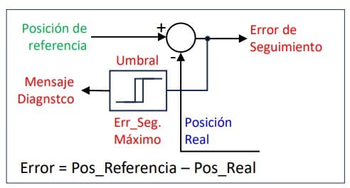
We can also come across other terms, such as Position Error, Following Error or Tracking Deviation, but the most used is tracking error. As already said, it is the difference between the theoretical position of the axis and the real one, as seen in the image. A threshold detector compares the error current value with the maximum tolerated value and if it exceeds it, it activates a warning so that the CPU acts according to the programmed code. The detection of the tracking error provides security and protection to the system; any failure of any type, mechanical or electrical, will trigger the tracking error since the entire axis is a closed loop.
Main causes of stoppages due to Tracking Error:
I am going to cite them in the order that I think they are produced the most, it also depends a lot on the OEM, if their mechanics are “fine” or they are one of those who want to make the car run with the handbrake on but based on my experience .
So, the order is not too relevant.
- Poor adjustment or no adjustment of the regulation loops. It would be a coincidence that the default values were a valid setting for the application, so it is possible that at low speeds the axis moves without blocking, but when the dynamics is increased it is not able to continue or also due to errors in configuration in the referred gear ratios and engineering units.
- Set dynamic parameters that the axis cannot reach On many occasions I have found programmers who set speed and acceleration parameters without knowing the maximum that the axis can reach. Many controllers already generate a specific overspeed error code, but in other cases they will stop due to tracking error.
- Mechanical problems: We must keep in mind that when we intend to make very fast and precise movements, not just any mechanics will do and many OEMs limit themselves to changing a self-induction motor for a brushless servo, without further ado, keeping the entire mechanical system intact. At this point some problems usually begin. That of the typical cheap gearbox that
has a tremendous friction torque, which was not considered during Servo Sizing. The lack of parallelism between the raceway and the spindle of a linear unit is usually another common one, also breakage of some component due to fatigue, couplings that are not well aligned, parts that have become loose and the shaft reaches the mechanical stop and much more.
Summary/Conclusions:
- Tracking error detection offers security and protection
- To be most effective, it is necessary to make a good adjustment of the regulation loops and subsequently a good adjustment of the threshold level.
- Until the axis is fully controlled – during initial start-up – it is advisable to adjust the error detection to low levels to prevent possible personal and material damage.
- In those applications in which the servo motor is rotating at a constant speed, such as rotary fillers, labelers, cappers, etc. Mechanical torque limiters can be eliminated. By limiting the motor torque to a value close to that necessary to rotate the machine and properly adjusting the following error, the program can perform measurements and reprogram values automatically, achieving better and more immediate protection.
- The value of the error in normal operation is a function of the adjustment of the position and speed control loops and of the dynamics of the movement, so it cannot be said which values can be “normal”.
- On a practical level, it is best to put the axis into operation under the most demanding conditions and use the trace tool to monitor the error value and set the threshold according to what is observed. A very dynamic speed loop will significantly reduce the error and if anticipatory gains are available, even better

Linkedin Pere Garriga