
There are still those who think of synchronizing axes with the concept that one is the Master and the other is the Slave, this comes from yesteryear when synchronization was by hardware. Nowadays, in PAC controllers, there are Virtual axes that allow us to do an infinite number of things, one of them is to synchronize axes.
This Tip explains why not to the Master Slave concept and yes to the virtual axes.
What a virtual axis is?
A virtual axis is the same as a real one, except that its position reference value is not transmitted to any physical servo drive. Therefore, it is not so virtual since the PAC has the same work of calculation that it has with a real one. I think it would be more accurate to call it the theoretical axis, this is irrelevant, but I think it makes it more understandable.
What are the Virtual axes used for?
- The main thing is to have a “pure” position reference source, mathematically perfect, which will allow us all kinds of synchronization of real axes.
- For applications where the use of transformations is needed, such as a simple connecting rod/crank and up to any geometry, from a SingleBelt to a delta robot.
- For phase control in applications where actual axis position needs to be phased to physical process marks that are captured by register inputs.
- To do motion control with frequency inverters connected in a field bus.
These are the main applications, at a generic level, but it can be the case of many others depending on the application.
Master / Slave Architecture.
A few decades ago, the only way to synchronize axes was by hardware. The servo drives had a pulse input, as a digital reference, to which a Master encoder or the encoder output, provided by the servo drive, of a Master axis could be connected. To understand the operation of a Master / Slave hardware synchronism, we will do it on the following scheme:
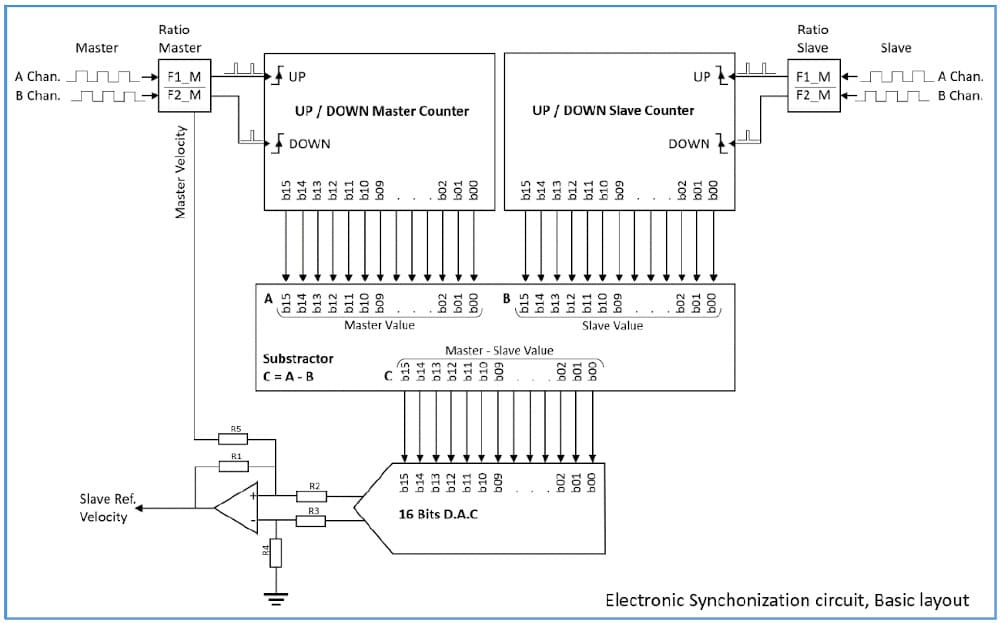
The signals of each axis can come from a physical encoder or be a replica of those of a servomotor generated by the servodrive. Each entry has a multiplier, whose value is programmed by means of a numerator and a denominator, so as not to accumulate errors in cases of numbers with decimals. With these F1 and F2 values for each axis, the desired synchronism ratio is set. In addition to establishing the desired ratio, the circuit is also in charge of decoding the direction of rotation and generating the appropriate signals (Up / Down) so that the counter increases or decreases and obtains the value of the real position of each axis.
The position values are sent to a subtractor circuit that obtains the difference between the position of the axes, which we could call the following error. If the synchronism were perfect, this value should be zero.
The following error result is converted to a speed reference value of ±10V by a DAC, digital analog converter, this value is added to the theoretical speed value of the Master axis, and the result is the speed of the Slave axis.
The real speed of the Master axis is obtained from the frequency of the encoder signal and is converted into a speed Feedforward so that when the following error is very close to zero, the Slave continues to have a speed reference.
This is the concept of the operation of a Master / Slave synchronism made by hardware, which used to be an electronic card external to the servo drives. Current servo drives already incorporate this functionality.
NOTE: The circuit shown does not correspond 100% to a real one, it is a version to understand the operation of an old hardware synchronism.
Given this, let’s go to a gantry system in which we synchronize the Y and Y’ axes with the Master / Slave concept.
The movement control that moves the Y axis, sends the reference -it can be of speed or directly of position, depending on the equipment used- and obtains the feedback of the real position of the axis, without having any connection or knowledge of the Slave Y axis. . On the other hand, the encoder output of the Y-axis servodrive (Sync OUT) is taken and connected to the Y’-axis servodrive input (SyncIN), which is configured to track the impulses of said input.

With this the Slave axis will follow any movement of the Master, including the small oscillations that are always present. The image shows the speed of both axes.
The main drawbacks of this architecture are three:
- The Y’ axis is “off-hook” from the Motion Controller, so no information is available and makes some processes more difficult to program and maintain.
- At the performance level, if we expand the real speed of the movement of the Y axis (Master) we will see that it presents a series of small oscillations, which is completely normal, but if we send this signal as a reference to the Slave Y’ axis, this it will try to follow it with the maximum fidelity and an amplifying effect will be produced that will cause a greater oscillation in the Slave axis, so the “fineness” of the movement will not be as desirable.
- The calibration process can be complicated, even if multiturn absolute encoders are available.
Virtual Axis Synchronization.
In this case, a PAC controller drives the two Y and Y’ axes through a field bus, so it has full control of both and all the information. The PAC program does not directly position any of these axes, but rather moves the YV axis, which is a virtual axis, on the other hand, both the Y axis and the Y’ axis are synchronized with a 1:1 relationship with the YV axis, hence
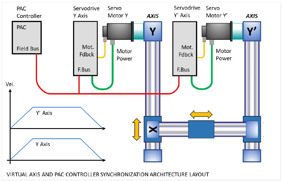
any movement of the VY axis will be reflected with full fidelity to the Y, and Y’ axes. In this case, with the virtual axis, a mathematically perfect reference is obtained, and the speed of Y and Y’ is achieved to be “totally” flat. In addition, the Y and Y’ axes can be moved individually for adjustment and maintenance operations.
In complex machines with a large number of axes, one or several virtual axes are usually used as “Master” and are synchronized, by means of electronic cams -CAM Profiles- with as many real “Slave” axes as necessary depending on the application.
Summary / Conclusion.
• The architecture in which a Slave axis follows the movement of a Master axis comes from when there were only specific electronic cards for this purpose, which were later integrated into the servodrives themselves. The main drawback is that the Slave axis is not integrated into the architecture like any other axis, on the other hand, at the performance level, the Slave tries to follow all the irregularities of the Master’s movement, which produces an “amplification” effect that It makes the speed not be as “fine” as it should be.
• In an architecture with a PAC, there are virtual axes that offer a mathematically perfect position reference. We will use this virtual axis as the Master of all the Slave axes involved. In this way, at the performance level, the fineness of the speed is improved, and all the axes are integrated into the system.
