
At times, movements using axis interpolation can be confused with movements using CAM profiles. This article explains how each of these movements is performed and summarizes their differences, showing some examples of application.
Interpolated Movements
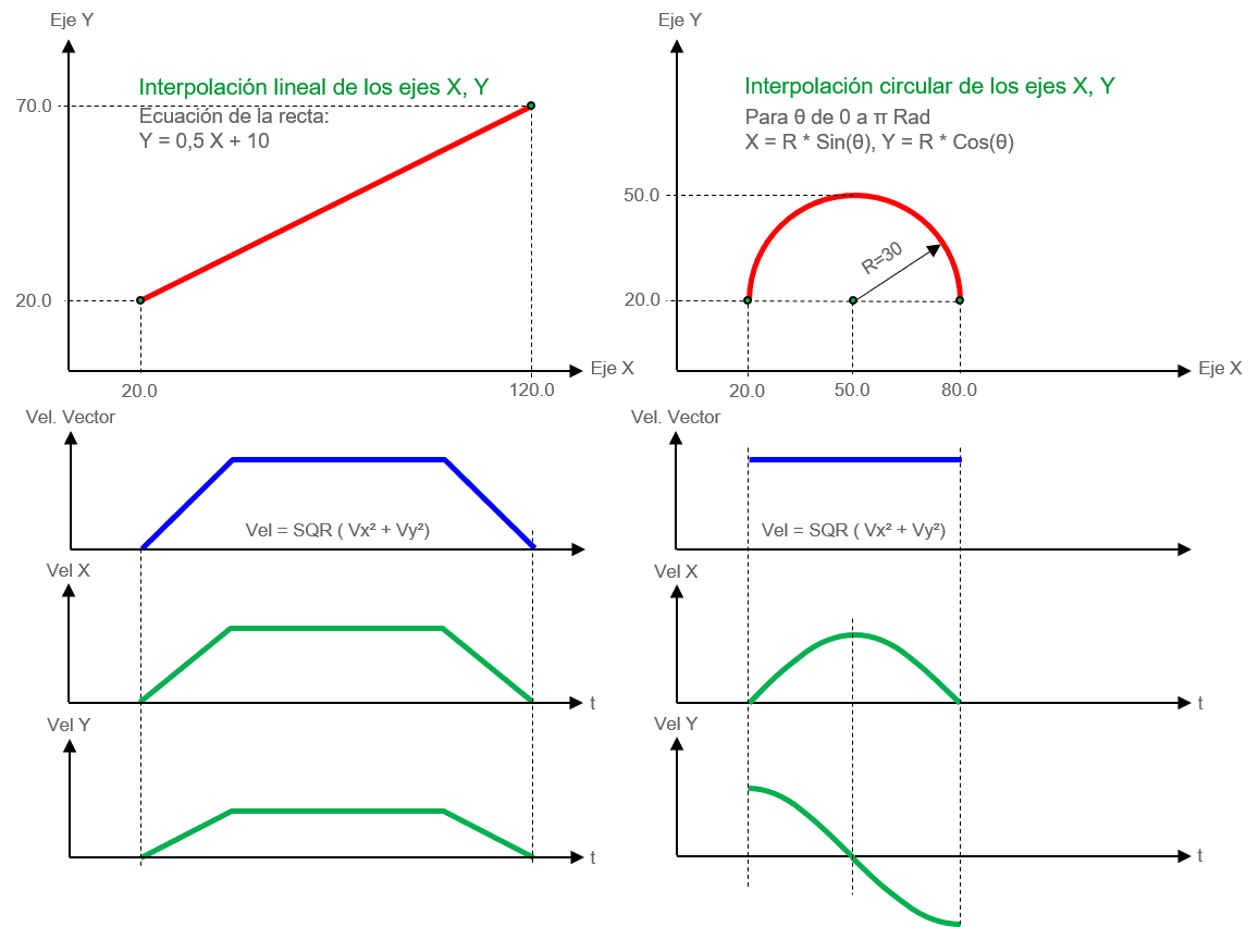
“It involves moving several axes simultaneously, so that the resulting movement describes a particular shape. The most common types of interpolation are linear and circular, although others such as splines are also used. The following graph shows linear and circular interpolations:”
What the control does to perform an interpolation
In the case of linear interpolation, the X, Y coordinates in 2D, or X, Y, Z coordinates in 3D of the target position must be indicated. In the case of circular interpolation, it is most common to define the arc of the circumference, by means of the coordinates of the destination point and a previous auxiliary point on the arc. In both cases, the parameters of velocity, acceleration, deceleration, and jerk of the resulting vector must be set.
With these parameters and using the equation of the line or circle, the PAC (Programmable Automation Controller) calculates the position of each of the involved axes in each interval of the motion control task (typically 1 mSec.) and transfers it to the servodrives through the fieldbus used, such as EtherCAT, SERCOS III, Ethernet/IP with CIP Sync.
It’s like positioning but involves multiple axes. The combination of the movements of the involved axes results in a straight line in 2D or 3D or circular movement, depending on the type of interpolation. This movement is not synchronized with any encoder or virtual axis but moves according to the programmed vectorial speed.
Note: The way the PAC performs the interpolation calculation is simplified but valid for understanding how an interpolation is performed.
Combining Interpolations to create a Motion Path
Many applications require the axes to follow a path (Motion Path) while maintaining a constant vector speed, as shown in the graph
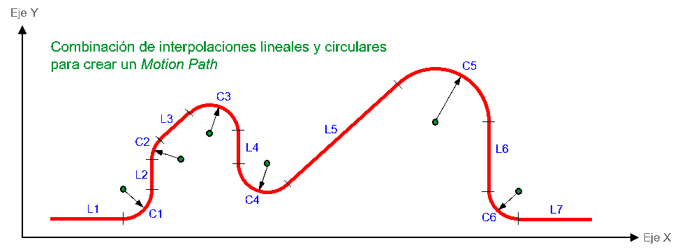
To achieve this, several linear and circular interpolation segments need to be programmed, in this example 13 segments are needed: L1, C1, L2, C2, L3, C3, L4, C4, L5, C5, L6, C6, and L7. Since it is necessary to know the next movement to maintain constant vectorial velocity, the PAC has a buffer to which the next interpolation must be “sent” before the previous one has ended. It should be noted that programming this motion path using CAM profiles would be very complex and inappropriate.
Explanation of a basic movement with CAM profile
This is about moving one or more axes synchronized with the movement of a master encoder or a virtual master axis. The following graph shows the conversion of a mechanical cam to a CAM profile (electronic cam).
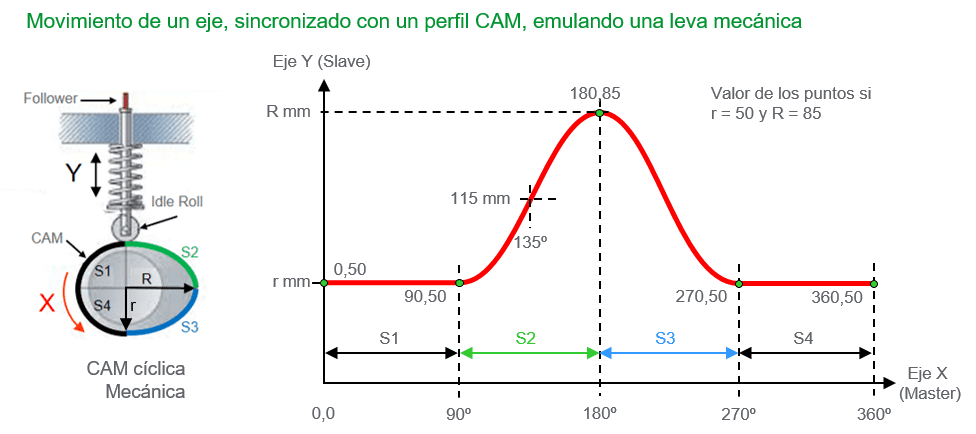
In this case, the CAM profile is “drawn” with the values of the five points (in green) that define the profile. Attached to the rotating axis of the cam is an encoder that provides the position of the X axis, or master axis, from 0 to 360 degrees. The X axis rotates through external means to the PAC control and the encoder provides the position value, in this case angular, with the encoder value, the PAC searches the CAM table for the corresponding position value of the Y axis (slave axis) and transmits it to the servo drive through the fieldbus, for example, when the master axis passes through 135 degrees, the reference position sent to the slave axis will be 115 mm (see graph). Therefore, the movement of the slave axis is completely dependent on the encoder position and the CAM profile values. Both the speed and acceleration will depend on the speed of the master axis (encoder), and the position of the slave axis will always be synchronized with that of the master axis, as if it were a mechanical cam.
Motion with CAM profiles in multiple axes
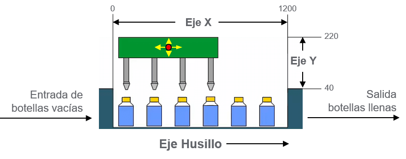
In this application example of continuous filling, it is necessary to synchronize the axes of the Cartesian robot, X and Y with each other, and at the same time with the spindle that controls the product feed rate, as shown in the following diagram.
The bottles advance at a constant speed (according to the recipe value) driven by the spindle axis. The carriage (in green), which moves the filling nozzles, has two axes of movement, X and Y. The cycle starts with the carriage waiting in its left position and a few mm above the bottles. It synchronizes its movement with the spindle axis while lowering the Y axis and inserting the nozzles into the bottom of the bottles. As they advance, the X axis remains in synchronization with the spindle, the Y axis gradually rises, and the bottles are filled. Finally, it rises to the waiting position outside the bottles, and the X axis returns to the initial point waiting for the next cycle.
In this case, the slave axes X and Y are synchronized with the master axis spindle and implicitly with each other because they are both synchronized with the same master.
The following graph shows the approximate shape of the CAM profiles for the X and Y axes.
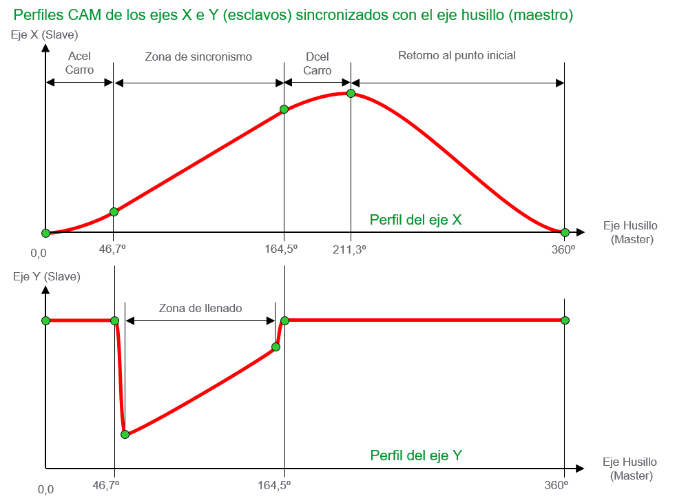
Once the carriage accelerates in X and synchronizes with the spindle, the Y axis can lower to the bottom of the bottle, and as the carriage advances, the nozzles rise until they come out of the bottle and remain in their waiting position. The carriage decelerates and quickly returns to the starting position for the next filling cycle. In these examples of CAM profiles, it is already evident that they cannot be solved by interpolating movements; it is necessary to synchronize the movement of each slave axis (Y, Y) with its master (spindle).
Summary:
● Interpolation combines the movement of multiple axes so that the resulting trajectory describes a straight line or an arc in a 2D plane or 3D space. The axes will move according to the programmed dynamic values for the resulting vector (velocity, acceleration, deceleration, and jerk).
● A motion using CAM profiles synchronizes the position of the axes, emulating the operation of mechanical cams, so that the position and speed of the slave axis depend on the shape of the cam and the rate set by the rotation of the master axis.
● The type of application determines which functionality is appropriate. If the application involves synchronization, then the solution will undoubtedly be through CAM profiles.
