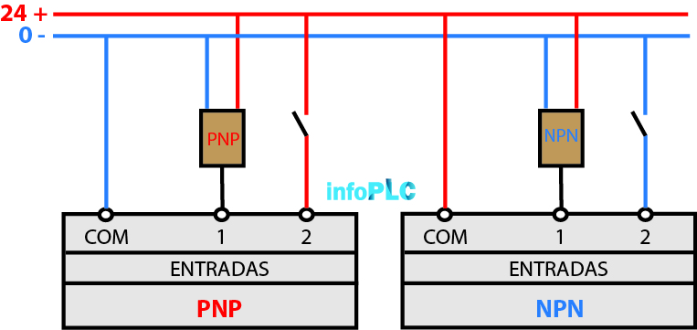
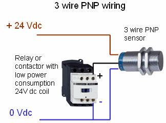
The PNP and NPN concept is something that we are going to come across throughout our professional lives on many occasions, when we have to select a three-wire detector or photocell, when selecting a PLC, and above all at the time to design schematics and wiring.
This concept is not always very clear, especially at the beginning of the professional career, over time when hearing these words your mind already visualizes the wiring corresponding to each element.
Difference between PNP and NPN
The difference between the two is marked by the design of its internal circuit and the type of transmitter used.
The difference that should interest us is the output. If we take a sensor as an example:
BROWN CABLE: + 24V power supply
BLUE CABLE: Power – 0V
BLACK CABLE: Output
 PNP - Positive Output +

 NPN - Negative Output -
When to use PNP or NPN?
There are several factors that can incline towards which type of output to use, but none of them is decisive, on the market there are sensors of both types as well as PLC cards.
In Europe it is more common to use PNP (sinking) while in Asia it is more common to find NPN (source).
An important aspect is the stock of material, as in Europe it is more common to use PNP it is always easier to find a larger stock of PNP material.
It is important before making a modification or extension to a machine or installation to be clear about the type of inputs it has.
As for the advantages … it seems that NPN is faster in switching since it works with 0V reference, it has less immunity to noise, less voltage drop.
PLC Input and Output Wiring
In general, the input cards of the PLCs are compatible for both PNP and NPN since it will depend on how we wire the common.
For this, there is a common (COM) of the input card, depending on whether we use PNP (COM -) or NPN (COM +) sensors, we must supply the common in a certain way.

If we refer to the outputs, here it is necessary to specify if we want it PNP (sinking) or NPN (source) unless the output is a relay.


