PLCs have become an integral part of manufacturing in the twenty-first century and now dominate industrial automation. To have a meaningful and successful career in the field requires a thorough understanding of the key foundational skills and theoretical concepts of PLCs.
The PLC Technician’s Handbook was developed to be a compact collection of fundamental content for practicing automation and PLC technicians to reference through their career. The handbook is broken down into three sections for easy reference: first, a series of articles including basic programming & tips and common practices, second, programming examples, and third, supplemental information such as instruction sets of the main ladder logic programming commands and important schematic symbols.
The world of manufacturing has been changing rapidly over the past decade. Processes are largely automated and as a result, the quality of products that are produced and the efficiency of systems that produce them is at an unprecedented level. Despite these changes, programmable logic controllers have remained a critical component of these systems despite being invented in the 1960s.
Processor or Central Processing Unit (CPU)
Often referred to as the “brains” of the PLC, the processor or central processing unit is responsible for the execution of commands. The industry has made an effort to use a standardized list of programming languages, namely:
- Structured Text
- Ladder Diagram
- Sequential Function Chart
- Instruction List
- Function Block diagram
What is a Scan Cycle?
Generally, PLC’s operate by repeating what is called a “Scan Cycle”. This cycle consists of four basic functions. First, the
inputs are read, next the program instructions are executed after which diagnostics and any required communications occurs, and finally, the outputs are updated. One important aspect of the scan cycle is the “Scan Time”. This is the total time it takes for the PLC to perform a complete scan cycle. This time can be critical in applications that require real time monitoring and control.
Why Ladder Logic Programming?
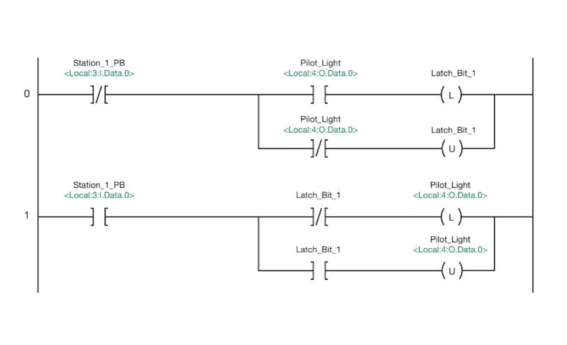
The primary reason ladder logic programming exists is that it allows technicians to easily interpret a PLC’s program by rendering the program in a format very familiar to technicians who have worked with relay logic controls prior to the advent and wide adoption of PLC’s. This programming language is very intuitive for those familiar with electrical wiring and relay control circuits and is easy to learn. Many technicians have worked with relays in the past. The physical device contains a coil, and one or more contacts that will change state depending on whether the coil is energized or not. This type of device is modelled in ladder logic programming by a OTE instruction, (serving as the coil) and one or more NO or NC contacts that are controlled by the coil.

