Because it reduces the power dissipated in the semiconductors (BJT, IGBT, MOSFET) to the level of just the losses.
It is explained in detail below
A little review of basic concepts:
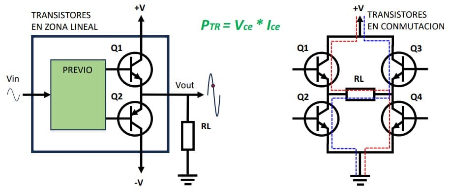
Transistors, regardless of their type, BJT, IGBT, MOSFET, etc., can operate in either the linear or switching region. To simplify things as much as possible, we could say that when they operate in the linear region, they are signal amplifiers, and when they operate in the switching region, they behave like solid-state relays or as contacts that open and close, as if they were switches.
Calculation of the power dissipated by a transistor
The power dissipated by a transistor is the product of the voltage between the collector and the emitter by the current flowing through the collector. In both modes of operation, as shown in the formula of the graph (green).
In the case of the transistor operating in the linear region, as an amplifier. Let us suppose that the voltage at the red point in the image is 200 V and the resistance is 24 Ω, a current of 200 / 24 = 8.33 A will flow. The voltage between collector and emitter (assuming that V+ = 400 V) will be 400 – 200 = 200 V. Therefore, the power dissipated by the transistor will be:
P = 200 * 8,33; = 1666,6 W; Which is a very high value..
Let’s see what happens in the case where the transistor works in switching mode. If we close the transistor Q1 and Q4, the RL resistor will be connected to +V and ground, therefore, to 400 V and a current of 400 / 24 = 16.66 A will flow. The voltage between the collector and the emitter will be that of a closed contact, 0V, but due to losses, an approximate voltage of 1.5 V will drop. The power dissipated by the transistor will be:
P = 1,5 * 16,66; = 25 W; This is a much lower value, and that’s even if we calculated it at 400 V, which in the previous case was at 200 V. But what good does this do me, if I can only turn the load on/off and what I need is a certain wave.
The PWM modulation
Thanks to pulse-width modulation, we can get the current through the load to have the desired waveform and frequency.
Let’s start with the most basic concepts. We start from a modulation frequency, which will be kept constant – a typical value in VFDs and servo drives of 4, 8, or 16 kHz. With this frequency as a basis, the output will be modulated in pulse width to achieve different average voltage values. The average voltage value will be its value multiplied by the % of the duty cycle.
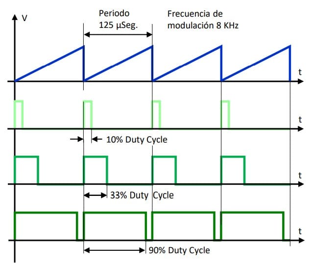
Assuming a DC voltage of 400 V, in the first case, with a modulation of 10%, we would obtain an average voltage value of 400 x 0.1 = 40 V. In the following example, with a duty cycle of 33%, we would obtain an average voltage of 400 x 0.33 = 133.2 V.
In the last case, with a duty cycle of 90%, we would have 400 x 0.9 = 360 V. Since we can change the duty cycle continuously, we can calculate it at each instant to obtain the desired average voltage value. The techniques for generating the signal will depend on the technology used, from a simple comparator with operational amplifiers, a FPGA, or a microcontroller.
Pulse-width modulation with an analog comparator
This circuit only intends to clarify the operation of a PWM modulation. There are many ways and circuits to achieve this, but this one is very easy to understand.

How to convert a square wave to analog
Converting those pulses that are varying their duty cycle to an average voltage value is the task of filters, normally low-pass, which will be responsible for eliminating the high frequency of the modulation signal and damping the square wave, converting it into a voltage level proportional to the pulse width. An example circuit could be something like the one shown below:
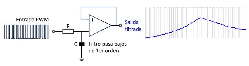
In this case, it could be an audio signal, or any other analog signal generated by this technique. In this case, the advantage is no longer related to the power of the semiconductors, but to the savings in analog circuits.
And in the case of inverters
When the load is inductive, such as in the case of an AC motor in a VFD or a brushless servo in a servo drive, which is practically the same, it is important that the shape of the current is as sinusoidal as possible. This is the responsibility of the motor windings themselves along with some LC filter inside the inverter.
In the lower image, the pulses of the voltage modulation of phase U can be observed, but however, the current in the image on the right already presents a sinusoidal shape.

Summary / Conclusions
- PWM modulation is what allows the manufacture of VFDs and servo drives,
because the transistors work in switching mode. - If the output of a VFD were a pure sine wave created with a function
generator and adjustable in voltage and frequency with a linear power
amplifier, it would be ideal. But there are no transistors of such power.